7
Fan coil units
MAJOR 2
A I R C O N D I T I O N I N G - R E F R I G E R A T I O N - A I R H A N D L I N G - H E A T E X C H A N G E -
N
N
A
A
0
0
4
4
.
.
5
5
0
0
1
1
B
B
D
IMENSIONS
OF
NCH
MODEL
I
WITH
DIRECT
BLOWER
Hydraulic connections
NOTE :
for satisfactory operation make sure to
respect a distance > 250 mm at the unit intake
MAJOR 2
NCH model
I
I
AE
AF
AG
AH
Mass
kg
Dimensional
drawing
426
765
505
535
400
26
7065443
428
965
705
735
600
30
430
1165
905
935
800
40
432
1365
1105
1135
1000
46
434 / 435
1565
1305
1335
1200
54
136
150
60
60
18
150
789
Air filter
disassembled
from rear
Removable panels for
access from below to fan motor
unit and coil
Sapcing between centres = 725
Pre-stamped hole
(accessory module)
Spacing betw
een centres = A
G
Blo
w
er cross-section
Oblong slots
12.7 x 25
Electrical
connection box
Evacuation
Sound-proofed expansion box
(ready to be against a wall with
foam seal accessory for fitting
under a structural beam)
75
A
B
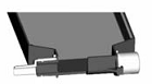
Double sleeve
A-B
A
water cooler
( 2 pipe system)
B
water heater
(4 pie system)
DET
AIL A
Reversible
connectors
Condensate evacuation
Ø15-16-22 et 28 mm
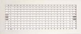
Rectangular discharge grille,
consult us